
Learn the ZSoil modelling workflow through the stability analysis of a 4 m-high cut. This tutorial introduces the graphical preprocessor, macro-modelling with semi-automatic meshing, analysis settings and the postprocessor.
Model: 2D plane strain · Data file: tutorials/cut.inp · Videos: 8
Geometry & Project Setup
Define the cut geometry and select the analysis type.
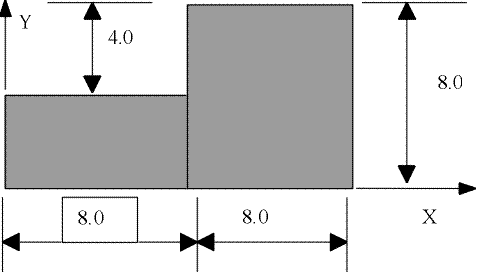
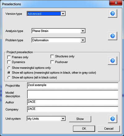
Choose File → New. In the project-preselection dialog, enable Plane strain and select Deformation as the problem type.
Material Properties
Represent the soil with a single Mohr–Coulomb elastic–perfectly plastic material.
Open Assembly → Materials and enter the properties shown in the table.
| Data group | Property | Unit | Value |
|---|---|---|---|
| Elastic | Young’s modulus, E | [kN/m2] | 40 000 |
| Poisson’s ratio, 𝜈 | — | 0.3 | |
| Density | Unit weight, 𝛾 | [kN/m3] | 19 |
| Non-linear | Friction angle, 𝜙 | [°] | 30 |
| Dilatancy angle, 𝜓 | [°] | 0 | |
| Cohesion, c | [kN/m2] | 16 | |
| Rankine cut-off | — | OFF | |
| Dilatancy cut-off | — | OFF |
Stability Analysis
Configure the strength-reduction procedure and its safety-factor increments.
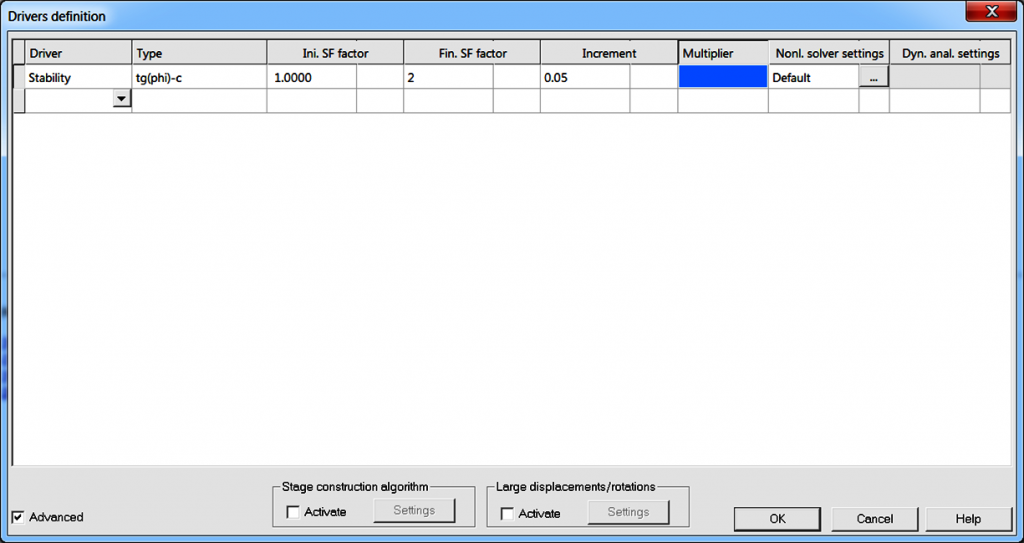
Open Control → Analysis & drivers. For this example, replace the default Initial state driver with Stability and select the tan(φ)–c reduction algorithm. Set the initial and final safety factors and the increment, then confirm with Modify.
The example starts at a safety factor of 1.00 and increases it by 0.05. Follow the computation through the successive reduction steps and examine the results.
Step-by-Step Videos
Follow the complete sequence, from creating the project to viewing the results.
1. Create a new project
Select the settings for a single-phase, plane-strain deformation analysis.
VIDEO
2. Create the macro-model
Define the geometry of the cut using the graphical preprocessor.
VIDEO
3. Generate the mesh
Create finite element meshes in the model subdomains.
VIDEO
4. Apply solid boundary conditions
Define the displacement constraints for the model.
VIDEO
5. Define the material
Enter the properties of the Mohr–Coulomb material.
VIDEO
6. Configure the stability analysis
Set the strength-reduction driver and safety-factor increments.
VIDEO
7. Run the computation
Start the analysis after completing the model preparation.
VIDEO
8. View the results
Examine the computed results in the postprocessor.
VIDEO
The screenshots and videos show the interface used in the original tutorial; menu names and appearance may differ in newer versions.